
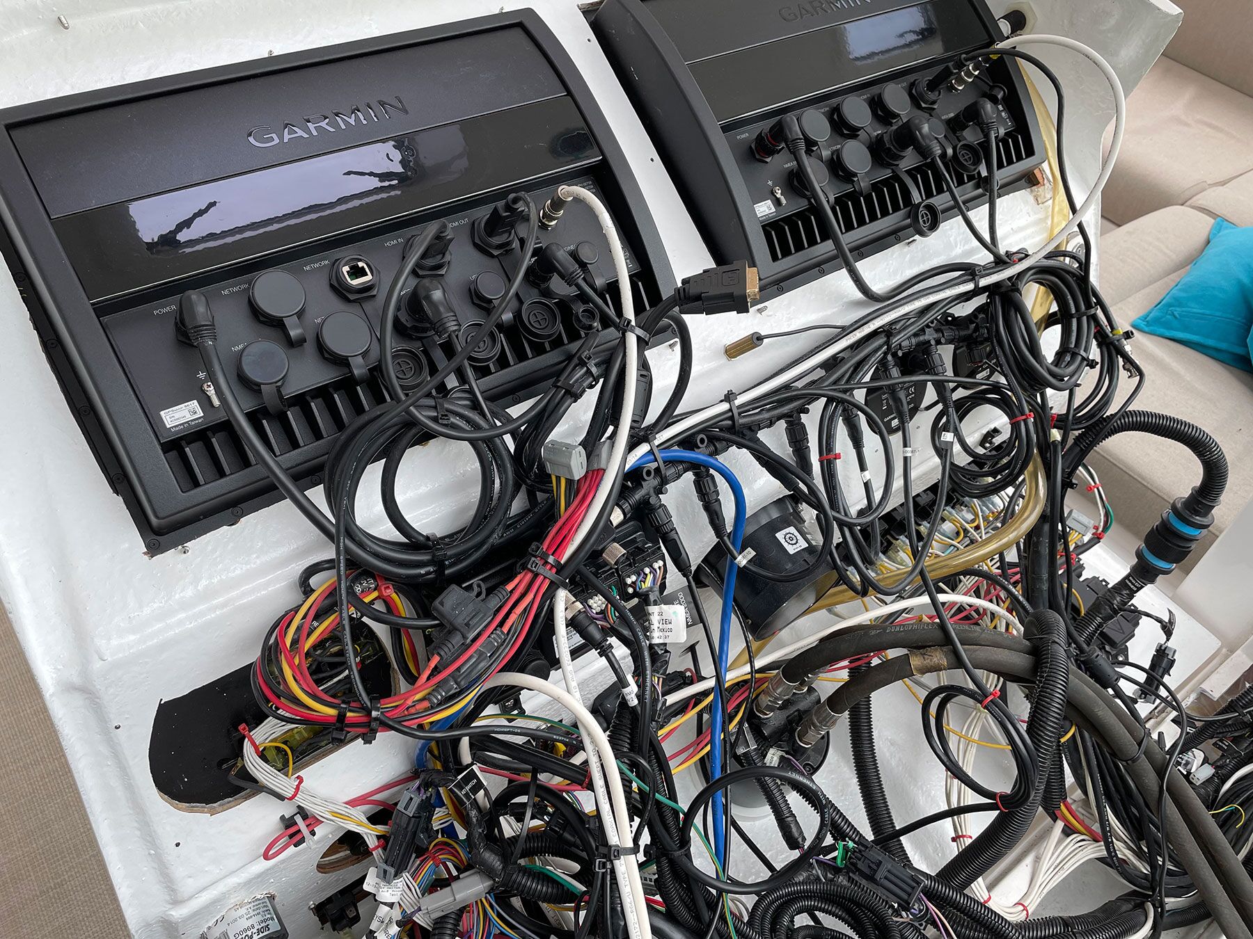
Navigational electronics have become more reliable, but also increasingly intertwined and complex. When failures occur, they tend to come in two varieties: data suddenly disappears from one or more devices, or the whole system goes dark.
If you cruise long enough, you will likely run into one of those scenarios. Let’s look at how different systems communicate and the troubleshooting possibilities to get your electronics back up and running.
Looking For Clues
Not too long ago, marine electronics consisted of single-function units that displayed narrowly defined information: radar on one display, location information on another, depth on another, and so forth. Some manufacturers started making it possible for data to be shared between units, say with main helm instruments and repeater units on the flybridge.
Then, manufacturers realized that combining information among different types of units could be useful: autopilots could steer to a waypoint established on a GPS; sending GPS information to a VHF radio could help transmit position data to the U.S. Coast Guard in an emergency; fuel flow and tank sensors could calculate remaining running time to show on a multifunction display.
Today, it is common to install a single display that shows all navigational data on one screen. Devices being integrated need to speak a common language for this to happen. The National Marine Electronics Association, founded in 1957, created NMEA 0183 and, more recently, NMEA 2000 for this purpose.
The NMEA also has a standardized Ethernet protocol called OneNet (nmea.org/content/standards/OneNet) that allows for speeds 400 to 4,000 times faster than NMEA 2000 (that means greater amounts of data can be shared for audio and video applications). Ethernet has another advantage: Up to 25.5 watts of power can be supplied on the network. This is called Power Over Ethernet, or POE. Some devices already use standard Ethernet cables for larger data transfers such as sharing radar information between displays. OneNet allows for a more durable, marinized version.
NMEA Language
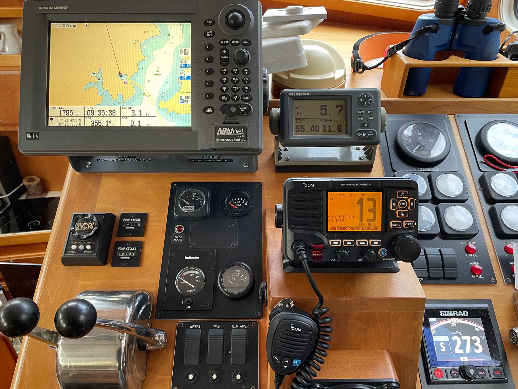
Quite a bit of rugged older equipment still functions well with the NMEA 0183 protocol, which is based on the idea of talkers and receivers. Each instrument has wiring pairs (positive and negative) for talking (transmit-TX or TD) and receiving (listen-RX or RD). NMEA 0183 allows only one talker at a time, but several receivers. A typical scenario might be a GPS giving position information to an instrument display, autopilot and VHF radio. The autopilot might then transmit heading information back to the GPS plotter on separate wiring, with the autopilot as the transmitter and the GPS as the receiver.
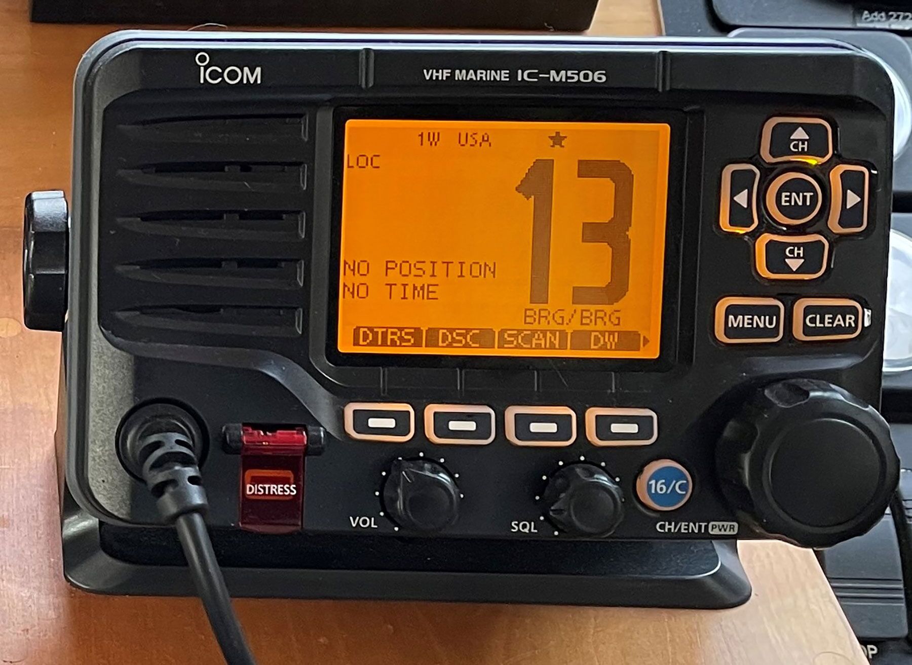
Unfortunately, many boat owners fail to make the wiring connection between their VHF radio and a GPS source, negating the VHF radio’s ability to send out position data in a distress situation. Manufacturers are starting to sell radios with built-in GPS capabilities for this reason.
System Backbone
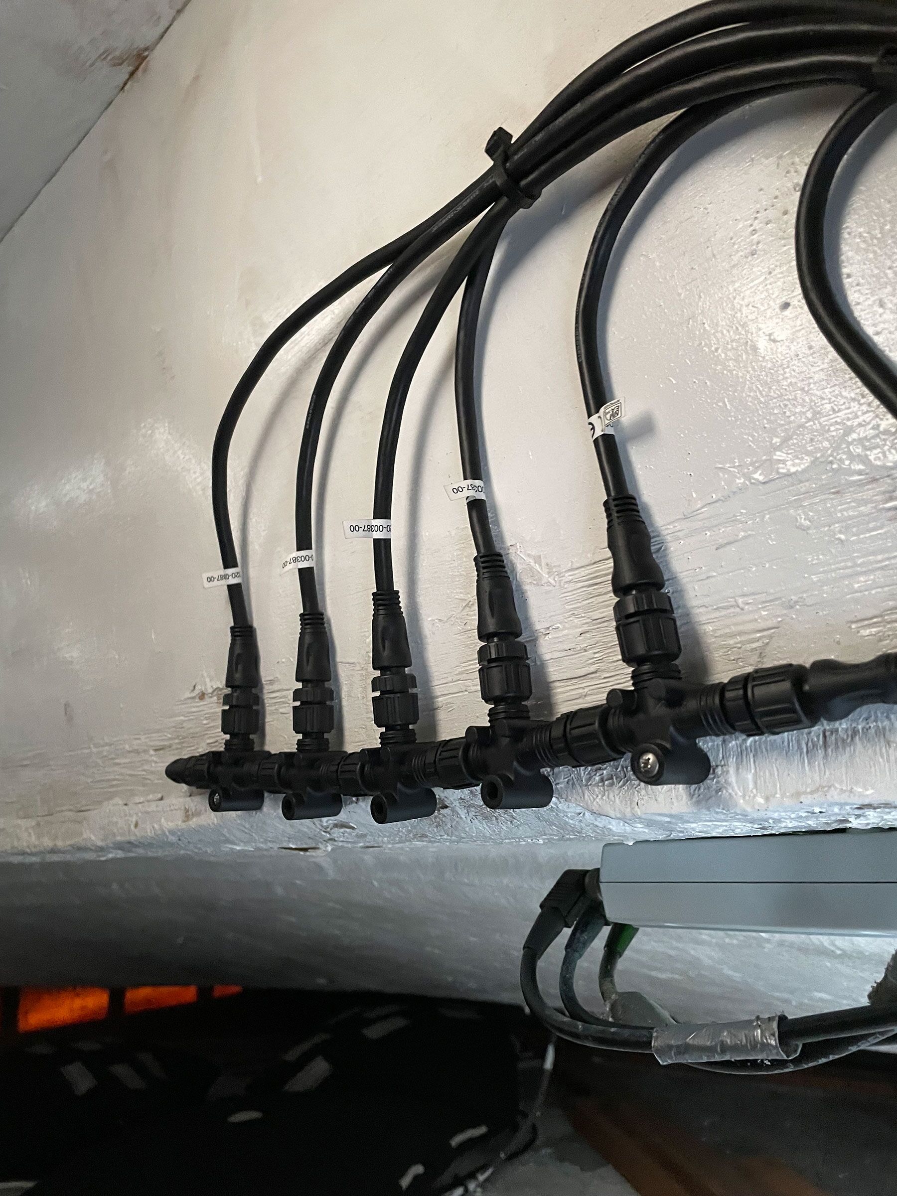
Unlike NMEA 0183, the newer NMEA 2000 can have talkers and listeners on the same wiring, which means data transmits faster. The system relies on a backbone of a central cable with T connectors and drop cables that connect to the individual instruments. This backbone, or main trunk line, needs a separate power source, usually supplied from the electronics fuse block. Knowing the location of that power source can be critical to solving a system failure.
Your system will perform more reliably if it complies with some best practices. The power supply should join the backbone from the center, not from one end, to lessen the possibility of voltage drop across a long backbone. The two ends of the trunk line require terminators: a fitting designed for that purpose. There are also limits to the cable length from the trunk connection to the instrument: just under 20 feet per drop, and 255 feet of combined drop length.
All wiring should have drip loops where possible to prevent water from running down a cable into a device. Like all wiring on a boat, the cables need to be secured against any movement or vibration.
Proprietary Languages
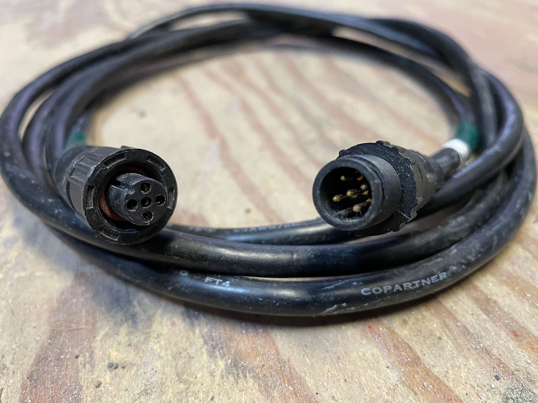
Along with the standardized NMEA languages, some manufacturers have their own languages, such as Raymarine’s SeaTalk or Simrad’s SimNet. Within these subsets are multiple versions that evolved as the equipment matured. Most manufacturers make converter boxes so newer equipment can talk to older gear. They also make converter boxes called gateways to convert their language to NMEA. Often, manufacturers sell proprietary cables and plugs as well.
Older depth, speed and wind display units were the power sources for their transducers. The head unit was necessary to interpret the data before it could be put on the network. Newer transducers are powered from the NMEA 2000 network and don’t need the head unit to interpret the data. This setup allows data to show up on any device on the network (although there typically needs to be a master unit that can calibrate that data).
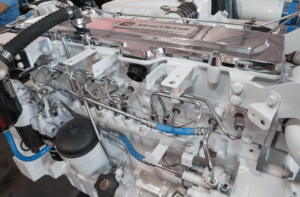
There has been a huge jump in the number of NMEA 2000-compatible sensors, as well as in display functionality to interpret that data. Many engines can now output NMEA 2000 for much of their running information. Some devices can transmit NMEA data to cellphones and tablets via local Wi-Fi networks.
Troubleshooting On NMEA 0183
Let’s assume you have an older system, and the individual instruments display the correct information but do not transfer that information. Troubleshooting NMEA 0183 requires some understanding of software and wiring.
The units will have input and output wiring, sometimes for multiple ports. Each output (TX or TD) and input (RX or RD) will have a pair of wires: a positive and a negative. The wires should connect at a terminal strip or block. Ring-terminated wires connected to terminal strips are preferred over bare-wire connectors or hard connections, to ease troubleshooting and lessen vibration resistance.
You can confirm data output with a multimeter set to volts, and with the probes on the output pair (positive and negative) of the bus. Your meter should jump between 0 and 3 volts, confirming that data is being transmitted. If the probes show no voltage, then look in the device software. There is often, but not always, a page where the output and sometimes input data can be turned on and off.
One of the most common connections can be found between the GPS outputting device and an autopilot. On many older autopilots, it will often look like there is no data transmission unless you plot a waypoint on the chartplotter and ask the chartplotter to go to that waypoint. Once the chartplotter is going to the waypoint, check the autopilot in navigation mode to see the waypoint listed, and to acknowledge that you want the autopilot to steer to the waypoint.
Troubleshooting On NMEA 2000
On a newer NMEA 2000-connected network, you may need to troubleshoot a loss of the entire system. Start by turning all components off and restarting. If that doesn’t solve the problem, then break out your multimeter.
Voltage should be checked at the source of power to the backbone, and at the network extremities. Voltage should be 14 to 9 volts, favoring voltages above 12. The male pins are easier to check than the female sockets unless you have tiny multimeter leads; be careful not to short the meter leads. Note that the pins in the sockets are always in the same order. Temporarily remove one of the end terminators and measure voltage with a multimeter on the S and C pins (see illustration). Field technicians often make up plugs with short wires stripped and exposed for easier testing.
If you see no voltage in the backbone, then check the fuse or breaker that powers the backbone. If the fuse is OK, then check the wiring connections at the fuse block. If you have voltage, but it is too low, then the supply wiring could be too small, there could be excessive length in the drops, or a device could be malfunctioning and pulling too much amperage. Try making the system simpler by removing Ts and drops until you find the culprit.
High resistance in the network can also be a problem. You can check resistance by powering down the network and removing one terminator. Check resistance between the H and L pins. It should be 60 ohms. If it is 120 ohms, the other terminator is missing. If it is 40 ohms, someone installed a third terminator, and it must be found and removed. If a third terminator can’t be found, then you may have a noncompliant device with an installed resistor that can be turned off within the device’s software.
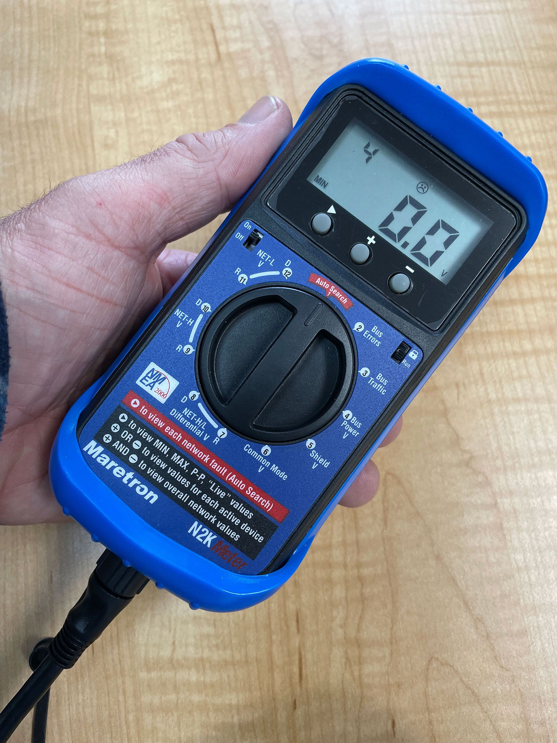
For more advanced troubleshooting, there are tools such as the Maretron N2KMeter and Digital Yacht NavDoctor. These tools plug directly into the backbone and provide helpful information.
Keep This In Mind
Modern navigational electronics can be intimidating, with hidden black boxes, NMEA backbones and interconnectivity. In most cases, a problem can be left unresolved until you have access to a professional, but a little know-how will let you handle basic troubleshooting on your own.
Remember: Loss of data points is not the same as loss of the system. Knowing what to look for, and how to find the information, gives you a good chance of resolving the problem and continuing your cruise.
This article was originally published in the May/June 2022 issue.