


It’s easy to tell if a bucket is full. But once you put a lid on it and make it a tank, it can be challenging to find out just how full it is.
The importance of knowing how much fuel, water or effluent our boats are carrying at any given time can’t be understated. If there is a straight shot from the fill down into the tank, a dipstick works well. Any other method, however, is going to require an engineering solution.
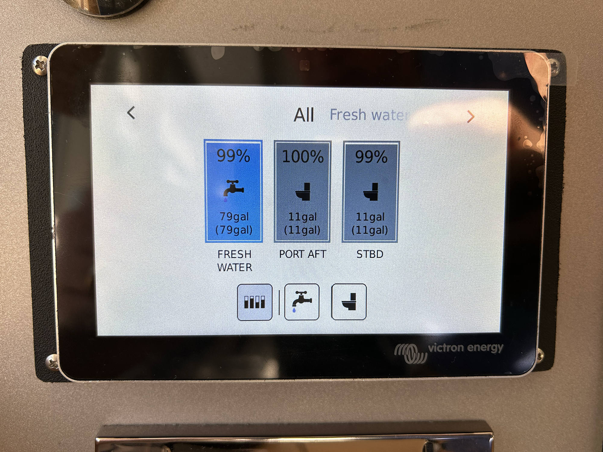 Photo: Max Parker
Sight Tubes
One simple and reliable option that requires no electricity is a sight tube. If the tank has a fitting at the bottom and top, and a clear tube is installed between them, then the tank fluid level can be viewed through the tube.
A proper sight-tube installation will utilize ball valves at the top and bottom, clear fuel-rated tubing, and some sort of protection for the tube to keep it from getting snagged or broken. Ball valves are favored over gate valves because you can tell at a glance if the valve is open or closed. If the valve handle is in line with the tube, then it’s open; perpendicular, it’s shut.
For obvious reasons, it is safer to have these ball valves shut when the level is not being read. If anything were to fall against the sight tube, it could rupture and send the entire contents of the tank into the bilge. Many engine rooms are tight, and it can be easy to catch a sight tube with an elbow, shoulder or tool in your back pocket. Because of this, it is a good idea to back up the tube with a metal or fiberglass cage.
The material of the tube is also important. If it is hose, then it needs to be rated for the liquid inside and at least start out as clear as possible. (I’ve never found a hose that won’t eventually discolor.) Glass sight tubes are available, and they stay clearer longer, but they require even more protection. Sight tubes do not work well for holding tanks and, well … ew.
Sight tubes are reliable and simple, but they do require you to be physically beside the tank in order to read them. To see the level of a tank remotely, you must install some sort of sender in the tank, and there must be a gauge that can interpret the sender.
 Photos: Max Parker
Tank Tender
The Tank Tender system utilizes the Archimedes principle to display the level of fluid in a tank on a round gauge. The system can be used for fuel, water and effluent.
A small plastic tube is installed in the top of the tank and is connected to the gauge via another airtight tube. The gauge has a small pump that pushes air into the tube, and the weight of the fluid pushes the gauge’s needle, showing how many inches of fluid are in the tank.
Note that overfilling the tank to deck level may add additional height to the water level than the gauge can read, creating a situation that can damage the needle or knock it out of calibration. Plugged tank vents can also over-
pressurize the system. As long as the tubes remain airtight and do not become plugged (which can be an issue with holding tanks), the device is a simple and reliable way to read multiple tanks.
Floats
Float-type senders are well described. These have a small float on either an arm or a stalk, or are contained in a tube that floats in the liquid. The position of the float moves a mechanical arm to vary resistance, or it triggers switches.
The reed switch was invented by W.B. Ellwood at Bell Laboratories for the telephone industry, but it is useful for us as well. It works with a sealed switch with two ferromagnetic blades almost touching. Inside the tank, a float with a magnet embedded in it floats up and down a rod. As it passes the reed switch, it makes a connection that causes a remote light to come on.
If you place several switches on the rod, you can monitor multiple fluid levels in the tank. Alternatively, several floats can be placed on different-length rods, each with a single switch. Since each float doesn’t have far to move, there is less chance of it getting stuck.
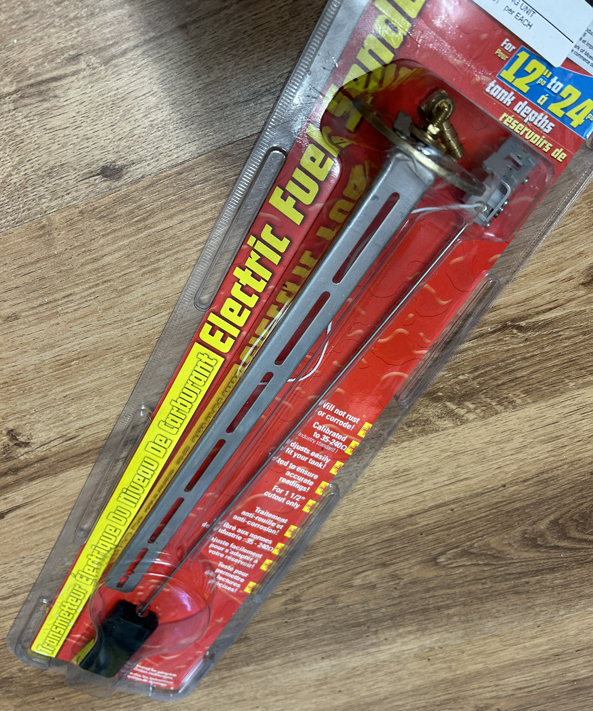 Photo: Max Parker
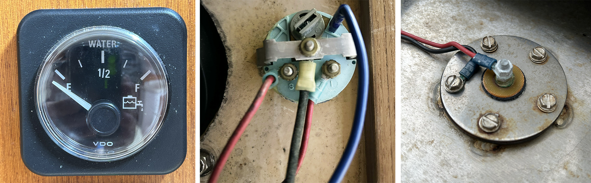
Another type of float sender has a stalk that fastens to the tank top, and a moving arm attached to the float. At the “elbow,” there is a varying resistor, which is a coil of very fine wire with a sweeper on it. One side is connected to ground through the tank attachment (or external connection).
As the sweeper passes different amounts of coil, the resistance changes. Traditional fuel gauges work by supplying positive DC to one side of another coil attached to a needle in the gauge. The other side of this coil runs to the sender. As the variable resistor in the sender changes resistance in the wiring (when the level of liquid changes), the needle at the gauge moves.
When troubleshooting this type of gauge, check for voltage at the back, between the positive and the “S” post. If there is no voltage, try jumping the “S” post to ground. If the needle jumps to full, the gauge is OK. Next, try removing the sender wire from the sender and grounding it to the tank. If the needle indicates full, then the wiring back to the gauge is OK, and the sender is likely damaged.
During sender installation, it is critical to measure the stalk accurately to get the “elbow” at the correct level for full articulation of the float. It’s a good idea to hold the sender beside the tank (this is more challenging in bilge tanks) while manually moving the float up and down. If you do this with the gauge’s wiring temporarily connected and a friend at the gauge, you can confirm that the needle in the gauge will have full motion. Be careful when you install the sender that the float does not hit the side of the tank, limiting its motion.
Note that standard 5-bolt hole senders have an asymmetrical hole pattern. Before removing or installing a sender, make a mark on the sender and on the tank so you have an index. There is nothing more irritating that getting four of the screws started only to realize that you somehow rotated the sender, so that the fifth screw can’t be started. To exacerbate this issue, tanks are often installed directly under decks, severely limiting your ability to see what you are doing.
Finally, be aware that tanks are often surprisingly thin. If screws are tapped into the surface, there won’t be many threads, and they can be easily stripped. Senders will come with a gasket to help seal, but you’ll want to use a fuel-rated sealant on the threads of the screws as well. Tanks need to be able to hold 3 psi of pressure before they leak, and this includes the sender seal.
Honestly, boatbuilders should build in access to the tops of their tanks for hose connections and senders. Hoses and senders will need to be replaced during the life of the boat, sometimes soon after the boat leaves the factory. (I’ve personally had to replace failed senders on brand-new boats.) Few things are more irritating than having to cut inspection ports in a sole above the top of a tank simply to change a sender.
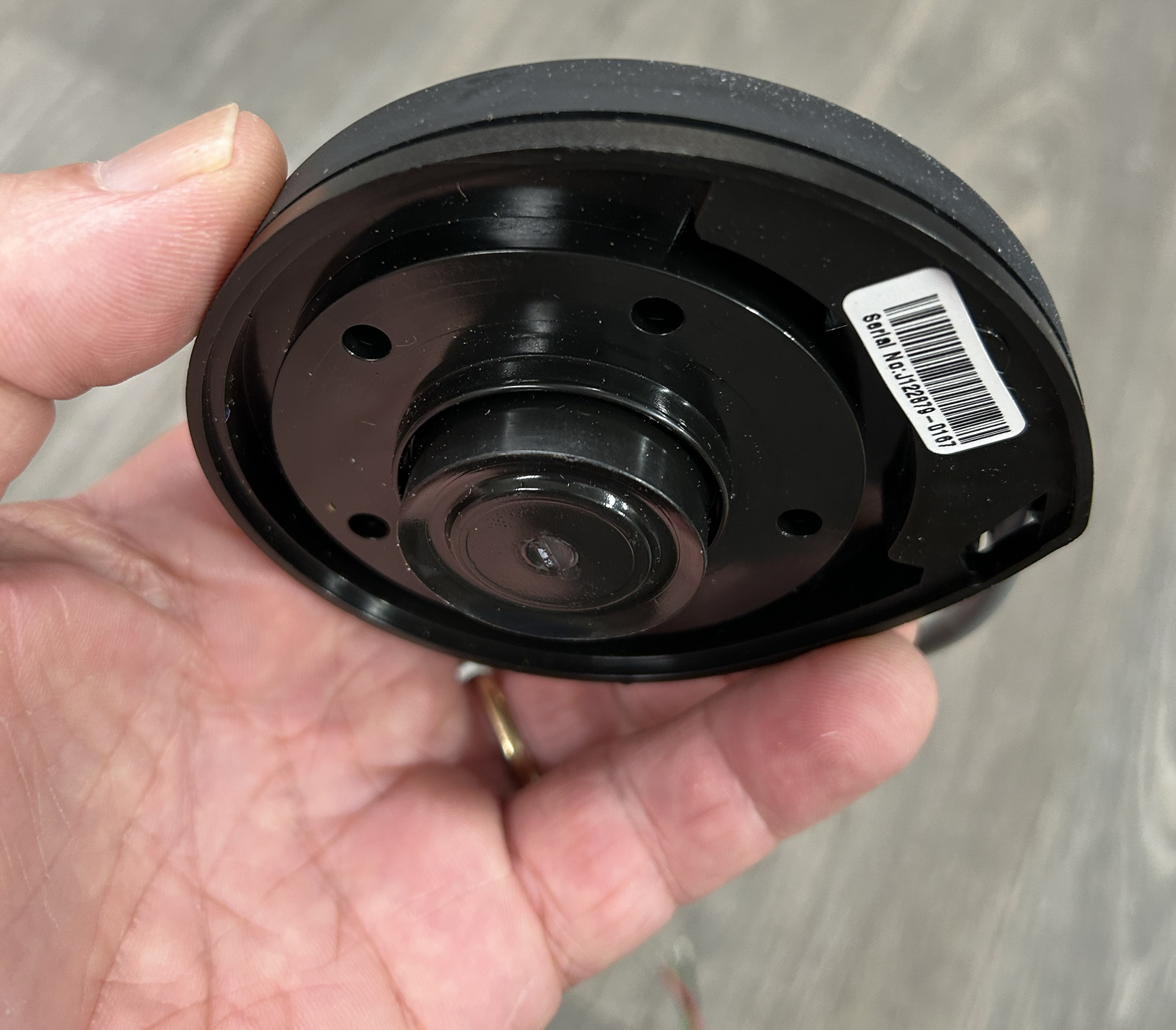 Photo: Max Parker
Ultrasonic Senders
Ultrasonic senders work much like depth transducers. They create a high-frequency sound that bounces off the top of the liquid and is then sensed to provide a reading. These are typically three-wire units, with one wire as the ground, another wire as positive, and the third wire providing the tank reading. Many utilize the standard 5-bolt installation, so retrofits are simplified.
It is important to pay attention to the wiring connections. Long runs with undersized wiring can cause the gauge to vary when large loads come online, and voltage drops.
Many ultrasonic senders can be used with standard gauges. Some will require converter boxes, while others will have calibrations built in. Most manufacturers of senders sell their own gauges, the advantage being that some can show multiple tanks on a single display, often with custom labeling. This can be a real advantage on larger boats with multiple tanks of the same liquid.
Pressure Senders
Senders designed to register pressure changes based on how much liquid surrounds them eliminate any moving parts and operate in fuel, water and sewage tanks, although some marine versions are sold that are only specified for water or sewage. These senders drop through a small hole in the top of the tank and are supported by their cable, which is sealed at the tank top.
External Senders
There are a variety of external “stick-on” senders that read through the tank to determine the fluid level. These cannot typically be used on metal tanks. They do have the advantage that they require no penetration in the tank, and they are not immersed in the liquid. Access to the side of the tank is required, however. Some external senders are only capable of reading water or waste, although the displays may be able to show resistance-reading mechanical senders for fuel.
Displays
Other than each manufacturer’s proprietary display, quite a few boats are coming from the factory with all the tank senders routed to a single multifunction display. This can easily be done with NMEA-enabled senders or with conversion boxes.
While this certainly is a clean look, a serious offshore boater will want redundant systems.
Calibration
If your tank is a standard box shape with no tapers or irregular features, then it is fairly easy to do the math to determine the liquid volume at different levels. Any variation in tank design, however, will require emptying the tank and pouring in measured amounts of liquid to calibrate the gauge.
Depending on the size of the tank, this can be done in 1- or 5-gallon jugs, or with the meter on a fuel truck and a well-tipped delivery driver. It is also nice to have a backup, so if a dipstick will fit into your tank, calibrate this at the same time. Similarly, mark your sight gauges if you have them.
Fuel Flow Devices
Boats traveling long distances without nearby fuel docks need to have accurate fuel-use data. Since engines use more fuel the faster the boat is pushed, you will need to create a table with gallons per hour usage at different rpm, or install a transducer in the engine fuel lines to measure fuel use in real time.
Most multifunction displays can now display this information if they are connected to the correct fuel flow transducer. Most modern computer-controlled engines are also creating this information to be displayed on their engine monitors or on the MFD. Some integrated systems will calculate the range of the boat based on the current fuel use and tank level—which is after all, the ultimate goal.
Checking Levels
Our first tiny cruising boat had understandably tiny tanks, none of which had gauges. We filled up the fuel in the bow and the water tank to port until we could see the levels coming up the fill hoses. The boat would then list to port. As the trip went on, we moved the fresh water to the holding tank, and the boat would list to starboard. The 8-hp diesel couldn’t use a whole tank of fuel in two weeks of puttering around, so it was pretty easy never to run out.
The only problem we ever encountered was when a landlubber guest overfilled the holding tank and blew the lid off. It would have been nice to have had a working gauge prior to that cleanup.


