INTRODUCTION
I’m a longtime cruiser of the Inside Passage, the Canadian waterway that connects Washington State to Southeast Alaska. I’m very comfortable aboard Intrepid, a Krogen 42 pilothouse trawler built in 1987. While she had a low-capacity 12VDC watermaker, I found that it could not keep pace with the demand. Producing less than 2gph, it simply postponed the inevitable dockside fill-ups by a day or so.
Besides, at such a low capacity, I had to run it for a long time to make it worthwhile. Then, there was the issue of water availability and quality along the British Columbia coast. The municipalities have abundant supplies, but no one wants to hang around towns just for water.
The First Nation bands also have excellent water treatment facilities, but during times of low supply they sometimes only allow access to band members. This leaves the remote marinas, which are few and far between. Their water comes from lakes and streams, and is untreated. While generally safe, each spigot is still posted with warning signs, so many boil water from these sources. Also, the cedar bark in the source water gives it a significant yellow hue. And during times of low water there is often a gritty residue left in the tanks. It seems all these problems have exacerbated over the years. So, what should be done?
An “off-the-shelf” watermaker can cost U.S.$8,000 or more depending on the capacity and features. It’s doubtful that I could ever recoup that cost on the resale of a 25-year-old boat—especially in today’s market. On the other hand, it might sell for that much less without an adequate watermaker. So, a commercial unit just doesn’t pencil out. That leaves doing it yourself (DIY).
The advantages are obvious. First, an advantage is the cost: about U.S.$4,500, or less depending on the features, if you don’t count your own time. Then there is understanding and being able to fix a system you designed and installed yourself. Commercial units often have numerous “bells and whistles” controlled by circuit boards. These are the components that seem most likely to fail and least likely to be fixable by the boat owner. Since a DIY is a custom design, you can scatter the components around your boat in a way that is most practical for you. You are not relegated to a box that may not conveniently fit in your boat. Finally, there is the satisfaction of taking a significant project all the way from inception to completion. The downside is time. The basic principles are not difficult, but it does take considerable time to design a system that meets the specifics of a particular boat. While all the components are readily available online or in your local hardware store, determining the precise specifications you need and sourcing them at the lowest price can be very time consuming. So much so that it is hard to imagine taking on this project in the “preinternet” age.
BASIC DESIGN: This is a “middle of the road” design. It makes water with minimal fuss. But, it is not primitive. It has electrically controlled system flushing, automatic salinity monitoring with rejection of “bad” product water, and automatic monitoring of the prefilters including ample warning if they become too restricted. All of this is accomplished with basic plumbing and wiring with only one electronic device – the salinity meter, which costs about $150 and can be bypassed if it fails. Everything else is pretty “bullet proof” and can be easily repaired or replaced if needed.
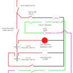
The premise of the basic watermaker is simple: Force raw (salt) water through a reverse osmosis membrane under high pressure. Keep the good water and toss the residual brine water overboard. (See Figure 1.) The devil is in the details.
I began by planning backwards from the predicted output at expected operating conditions. The output depends on water temperature, salinity, pressure, membrane surface area, and raw water flow rate.
Temperature and Salinity: All reverse osmosis membranes are tested and rated for 77degrees Fahrenheit (25degrees Celsius) water temperature; but their efficiency diminishes rapidly in colder water. The standard Filmtec SW30-2540 membrane used here produces 700 gallons per day at 77 degrees Fahrenheit,but it only makes
Figure 2: Membrane Efficiency
435 gallons per day at 55 degrees Fahrenheit, a typical summer water temperature in the Pacific Northwest. (See Figure 2.) This effect is offset, somewhat, given that colder water is less saline, (i.e., it has a higher concentration of fresh water).
Pressure and Surface Area: All membranes are tested at 800psi (55 bar). The FilmTec SW30-2540 membrane has about 30 square feet of surface area.
Raw Water Flow Rate: Within limits, more water in contact with the membranewill result in greater production. The maximum allowed flow rate of the membrane is 6.0 gal/min. (If the flow rate is too high the raw water will not be in the pressure vessel long enough to be forced through the membrane with maximum efficiency.) I will use a CAT 247 pump, which pushes 3.6 gal/min at 800 psi. A pump with a higher flow rate would require too much power to operate. (See Section G.)
So, our system will be about 8.4 percent efficient. In other words, it will convert about 8.4 percent of the water flowing though it into fresh water: (435 gallons per day) ÷ (3.6 gallons per minute × 60 minutes × 24 hours). Altogether, I can expect a production of about 18 gallons per hour (3.6 gallons per minute × 60 minutes × 8.4 percent). Since Intrepid consumes about 20 gallons per day, I will need to run the system a little more than an hour per day to keep the tanks full.
It turns out that the only real variable, in practical terms, is the membrane surface area, which can only be increased by using bigger membranes or more of them.
SYSTEM COMPONENTS: I will discuss the system components, in turn, beginning with the raw water intake.
A. Seacock and Strainer:By all means, use an existing through-hull, seacock, and strainer if possible. It does not necessarily need to be dedicated to the watermaker, but it should not be shared with any system that will draw sea water at the same time as the watermaker. This leaves out the main engine and generator. Intrepid has a conveniently located through-hull for its reverse cycle heat pumps, which will never be run simultaneously with the watermaker. It should also have an intake hose of sufficient size to serve the pumps.
B. Pickling “Y” Valve: I will need to draw in a solution of sodium metabisulfite (most cheaply available at any brewing supply store) or propylene glycol (nontoxic antifreeze) to “pickle” the membrane while it is not in use during the off season or other protracted periods. I put a “Y” valve in the raw water intake hose before the feed pump to pump the solution from a 5-gallon bucket.
C. Feed Pump: Now it starts to get more complicated. The feed pump pushes sea water through two prefilters then on to the high-pressure pump, which requires a minimum of 3.6 gallons per minute of supply water. A simple Jabsco 12VDC Water Puppy impeller pump (6 gallons per minute) is sometimes used, but, while self-priming, they have at least three drawbacks. First, the motor turns a shaft, which penetrates into the pump body through a lip seal. Eventually, the seal will break down and water will enter the motor. Second, at about 7psi it may not produce sufficient pressure to overcome minor fouling of the prefilters. Third, the impellers require periodic replacement. A better choice, but at more than twice the cost, is a magnetic drive pump. It has no shaft or seal. The motor spins a magnet, which, by induction, spins a second magnet mounted to the ceramic impeller encased inside the pump housing. Since there is no seal to malfunction, the pump is virtually maintenance free. It was hard to find a pump that would provide both sufficient flow and pressure. Then my boating friend Stan Heirshberg suggested I use pumps that circulate water in large aquariums. These pumps have to do the same thing—push a lot of water through filters that can get clogged up with marine growth. I chose the Blueline 70 HD external water pump (See Figure 3), which will provide about 12psi at 4 gallons per minute. ($250 from Aquacave, www.aquacave.com.) Its only downside is that it requires 110VAC power.
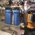
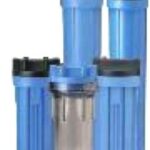
D. Prefilters: It is important to remove as much material from the water as possible before it gets to the RO membrane. So, I plumbed pair of ordinary household filters after the feed pump—a 20-micron filter followed by a 5-micron filter. Do not use paper (cellulose) filters. They will break down in sea water and shed particles
onto the membrane. I chose the pleated synthetic type with a good quality core by Flow-max. They can be cleaned for reuse several times. Siemens (www.thepurchaseadvantage.com) has a great selection to choose from with guaranteed low prices. Filter changing will be the most frequent maintenance task, so choose an easily accessible location for installation, and be sure to allow enough space below the canisters for their removal.
E. Low-Pressure Protection:The high-pressure pump pushes 3.6 gallons per minute and requires a flooded head. Its wetted parts are lubricated by pumped water. If the pump runs dry, it will damage this expensive component. (See Section F.) Therefore, it is important that there is a means of monitoring the raw water pressure feeding the pump and of protecting the pump against loss of feed pressure.
The high-pressure pump switch gets its power from the feed pump switch. In this way the high-pressure pump cannot run unless the feed pump is running first. Both pump switches are 12VDC but both pumps are 110VAC, so each pump circuit has a solid-state relay between its switch and its pump. This also helps cut down on the length and gauge of the 110 wire runs. The relay for the high-pressure pump should be mounted on a heat sink provided by the relay manufacturer. The feed pump relay does not draw enough current to require a heat sink.
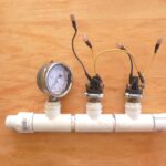
Plumbed directly into the 5-micron filter housing is a manifold consisting of a 0–15psi pressure gauge (PGM-63L-30V/-1BAR from www.omega.com, which allows pressure monitoring over time. As the filters begin to foul, the pressure will drop giving a “heads up” for a pending filter change.
For protection against unpredictably rapid filter fouling, I took some additional measures. (See Figure 5.) Following the pressure gauge are two 12VDC pressure switches, a 1–3psi then a 0.5–1psi A6-251221 and A6-151221 durable pressure switch from http://www.dwyer-inst.com/. Both are adjustable within their pressure ranges and both can be wired as normally open (NO), normally closed (NC), or both. Both switches get their power from the high-pressure pump switch on the control panel. The pressure on the first switch is set at 3psi and it is wired “normally closed” to a warning light on the control panel. Under operating pressures the switch is “open“ (no power to the light), but when the pressure drops below 3psi the switch closes, illuminating the warning light, which means it’s time to change the filters. The second switch is set to 0.5psi. The “normally closed” side of the switch is wired to an audible alarm on the control panel. At operating pressure the switch is “open” (no power to alarm), but at 0.5psi it closes, sounding the alarm. (Note: It is easier to set the operating pressures on the switches prior to installation because there is no easy way to create precise pressures with the feed pump after installation.) My original design had the “NO” side of the low-pressure switch wired to the high-pressure pump relay. My thinking was that the pump would shut down if the pressure dropped too low. But, I learned that as the pressure dropped to the switch’s threshold, the switch, and hence the pump, cycled on and off. So, now the switch only activates the alarm, which I have found gives ample warning.
The manifold was made from three 3/4-inch PVC tees (schedule 40) glued together in series. 3/4-inch-by-1/4-inch threaded reducers were inserted into the branch of each tee. Then, the pressure gage and
switches were screwed into the reducers. Finally, 3/4-inch threaded adapters were glued into each end of the manifold to accept the filter housing and the connection to the high-pressure pump.
F. High-Pressure Pump: At 20 percent of the total project cost, the high-pressure pump is the single most expensive component of the system. Some particularly price-conscious boaters have used ordinary pressure washer pumps, but have regretted it. Salt water under high pressure is very corrosive and those units are made for fresh water. A durable pump has to have 316 stainless steel or NAB (Nickel-Aluminum-Bronze Alloy) wetted parts. Discussing 316 stainless steel versus NAB is like arguing religion or, worse, anchoring, but here it goes. 316 stainless steel is very expensive, but it is still subject to crevice corrosion. NAB is about half the cost and is still very durable. It is hard to know which material is most cost effective in the long run.
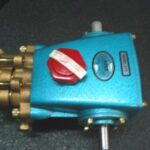
In any event, the pump has to provide a minimum of 800psi and ample flow up to the 6 gallons per minute that the membrane can tolerate. I chose the CAT 247 pump (http://www.catpumps.com/select/pdfs/231.pdf), which is a NAB pump (See Figure 6) available from EDI Distributors (http://www.edidistributors.com), which cost U.S.$877 versus U.S.$1,547 for 316 stainless steel. EDI has some of the best prices and provides excellent pre- and post-purchase advice and support. (For more information email Skip at info@edidistributors.com.)
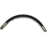
CAT makes excellent pumps that are widely used on a variety of industrial applications including a majority of pressure washers. Since it is a tri-plunger pump the 247 does produce considerable hose vibration, so I teed a less expensive pulse hose into the pump outlet port to take up much of the vibration (see Figure 7). The pump, drive motor, and its base were also attached to rubber mounts to help reduce the pump’s noise. The 247 pushes 3.6 gallons per minute at up to 1200psi, so it can handle the required 800psi with ease. There are also other pumps available, including the quiet Hydra-cell pumps. They are excellent, and very expensive.
G. Powering the Pump: Now, it’s time to power the pump. One way to do it is to drive the pump off the main engine or the generator engine. This can be done, but at a price. First of all, an electric clutch is necessary to have, otherwise the pump will run nonstop. Adding in the cost of fabricating pump mounts, brackets, sheaves, etc., and an engine drive can be more costly than an AC motor. Besides, Intrepid has a hydraulic bow thruster pump already hanging on the flywheel sheave so there is no room for another device.
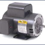
Also, with an engine drive you can only make water when the engine is running. Since the engine runs at various revolutions per minute (rpm), the pump will also turn at various speeds. That creates problems for pressure regulation. (See Section K.) Since I have ample generator capacity, I chose a 110VAC motor drive. The downside is I can only make water at the dock or with the genset running. But, how much motor is needed? The standard formula for the required horsepower to drive a pump is gallons per minute × psi ÷ 1460. So, at 3.6 gallons per minute and 800psi, a 2hp motor will do the job. (The motor will require about 1,500 watts from the generator.) The pump is geared to turn at 1725 rpm, so the motor speed has to match.
EDI recommended their #2550, a 2hp Baldor at $298. It can also be wired for 220VAC (see Figure 8). Also needed were a flexible coupling (CAT #8215), a bell housing (CAT #34121) to join the motor and pump, and a safety cover (CAT #25130) for the pump shaft not in use. A Pop-off relief valve (CAT #9960) is also good to have. It is plumbed into the second pump outlet port and set for 1000psi to protect the RO membrane. The valve “pops” open to relieve excess pressure.
H. High-Pressure Components: Everything between the high-pressure pump and the pressure regulator must be capable of withstanding the 800psi of pressure involved. Wired R2 hydraulic hose is rated for water and up to 3000psi, giving an almost four-fold safety factor. Since the pump outlet ports are 3/8 inch, so is the ID of the hose up to the pressure vessel. The outlet ports on the pressure vessel are 1/4 inch, so the hoses between the vessel and the pressure regulator are also 1/4-inch ID. The hose is not very costly but the 37-degree JIC fittings and adapters must be 316 stainless steel and are very expensive. Together, they made up 18 percent of the project cost. For example, a single 1/2-inch female NPT and 3/8-inch female JIC was $113. If you know the exact hose lengths needed, you can have your local hydraulic shop make them up using 37-degree JIC ends you provide, if they do not have stainless steel in stock. Since I built the unit away from the boat, I chose to use R2 reusable end fittings that can be attached to the hose with ordinary hand tools. They are about 30 percent more expensive than regular fittings.
Part descriptions and numbering can be confusing. I liked the clear descriptions on this website:http://www.discounthydraulichose.com. There are other good firms such as http://shop.hoseandfittings.comthat offer competitive prices, good communication, and reputable service. One good strategy I discovered is to determine the standard “Parker type” part numbers, and then search the Internet for the number instead of the item description.
I. Reverse Osmosis Membrane and Pressure Vessel: This is what makes the water. The membranes come in various diameters and lengths with pressure vessels to match. The membrane is essentially a coil of synthetic material with a hollow core (think of a paper towel roll) with pores so small that it excludes salt molecules but allows the smaller water molecules to pass. The high pressure outside of the membrane forces water molecules to go in and out of the central core. Be sure to select a membrane rated for sea water. FILMTEC, a DOW company, is a leading manufacturer of such membranes. Their SW30-2540 membrane is a standard size (2-1/2 inches by 40 inches), but diameter sizes are available up to 8 inches. I purchased mine from Siemens (www.thepurchaseadvantage.com) for $164.
It’s important to select a pressure vessel with a sufficient pressure rating. PVC housings are available but are not rated for 800psi. Stainless steel vessels are also available but I don’t see the advantage, given the price. I purchased a 1000psi fiberglass pressure vessel by HCTI with aluminum end caps, both from American RO (http://www.americanro.com) for $330. If space is limited then 21-inch membranes and vessels can be plumbed in series. Also, think about unused spaces for the membrane and housing—under settees, in the back of lockers, etc. I secured the housing to the overhead in the engine room.
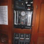
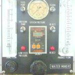
J. Control Panel: There is a lot going on behind the control panel. It holds the pressure regulator, high pressure gauge, salinity control meter, two flow gauges, plus various fittings, adapters, switches, lights, and alarms, all connected with hoses and wiring. In this case, they all have to fit into a small 9-inch-by-8-inch-by-9-inch space. So, I made a mock-up from 1/8-inch hardboard and fiddled with things until I was convinced I had it all right. To make the final panel, I used Front Panel Express (http://www.frontpanelexpress.com/), a DIYer’s dream. I downloaded their free software and used it to select the material and finish, as well as the shape, size, and location of all the holes and cutouts. Next, I chose the fonts and colors for all the engraved lettering. One click gave me an itemized cost and another sent it off to their CAD/CAM facility. Five days after the order was received, it was ready for shipment. A very professional-looking panel cost just a little more than $80.
In Figure 12, the high-pressure brine water enters the pressure regulator (the needle valve centered at the bottom) via the black hose (lower left). Its pressure is measured via the second black hose by the gage (top center). The brine water exits the regulator at low pressure, then enters the raw water flow gage via the white Watts Quick-Connect fittings (bottom right). Then, the brine water exits overboard via the green fitting (top right). Product water enters its flow gage via the blue fitting (center left) and exits to the tank via the yellow fitting (top left). Its salinity is measured by the meter (the white rectangle in the center) via an electrode (not shown) in the hose after the yellow fitting.
Components K – N are all situated in the control panel
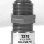
K. Pressure Regulators and Gauge: Somewhere downstream from the pressure vessel is the regulator, which creates the back pressure necessary to operate the membrane. It must be stainless steel, of course. The valve that does this work must be able to create the necessary pressure while allowing sufficient water to pass through. If an engine-driven pump is used, then the pump speed will vary with the engine speed and, hence, the pressure will vary too. But the membrane requires a constant 800psi to function properly so a regulator that maintains a constant pressure with varying pump speed is required. The CAT 7370 pressure regulator is excellent (see Figure 13). EDI has it for about $310.
I chose to use a 2hp electric motor turning at a constant 1725 rpm to drive the pump, so I do not face the problems presented by a variable speed drive. I wanted to use a relatively simple needle valve-type regulator, but the problem is there is a constant interplay between the pressure and the flow rate. The valve coefficient (or valve constant) is a measured quality that allows valves of different sizes, types, and manufacturers to be compared. It is the flow, in gallons per minute, of water that a valve will pass for a pressure drop of 1psi. For water, CV= Q(1/∆P)1/2 where Q is the flow, in gallons per minute, and ∆Pis the pressure drop. So, for a flow of 3.6 gallons per minute and a ΔP of 600 to 800psi, a
versus handle turns for each valve. I chose a Noshok 1/2-inch 404 FFS (http://www.noshok.com) available for $103 (see Figure 14). Its graph indicates a C
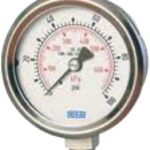
A high-pressure gauge monitors the membrane pressure, which should stay at about 800psi and should not exceed 1000psi. All its wetted parts must be stainless steel, and it should be glycerin filled or have technology to prevent the needle from jumping with the pulsation of the pump. WIKA 232.53 pressure gauge (http://www.dfs-gauges.com/products/9768246) is a good choice for about $44.
L. Flow Gauges: Technically called rotameters, these measure the flow of the raw and product water. The raw water flows at 3.6 gallons per minute and the product water flows at 18 gallons per hour, so the two gauges need to have different scales. Dwyer makes good ones—the VFB-86 and VFB-83 gauges. The pair came to about $100. These are 6-1/2 inches tall, but they also make them in 4-inch models.
M. Salinity (TDS) Meter: The watermaker’s first round of water production should be discarded until the salt content is at an acceptable level. The average “salinity” (total dissolved solids) of seawater is about 35,000 ppm (3.5 percent). It is said that the average person can taste as little as1000 ppm. My household water (we have a water softener, which actually adds a little salt) tests at about 300 ppm.
The water from our “under the sink” RO unit checks in at 7 ppm. So one way to know when the product water is ready for consumption is to taste it, or you can purchase a simple handheld TDS meter for $20 or so. I chose to include an electronic TDS meter (see Figure 17), which continuously tests the product water and rejects it overboard if the salinity exceeds 200 ppm. (The rejection set point is adjustable from 0 to 999 ppm.) At $150, Omega Instruments’ CDCN204-12VDC meter is a small price given the overall cost of the project. It consists of a small meter with an electrode on a cord. It can either be 12VDC or 110VAC powered.
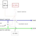
I chose the 12VDC option, which comes with an AC/DC converter at no extra cost. But since I wired the unit directly to the boat’s 12VDC supply, the converter was superfluous. The electrode is bathed by the product water. If the TDS exceeds the set point an internal switch closes sending a 12VDC signal current. The signal illuminates an alarm light on the control panel, and also energizes a pair of solenoid valves that route the “bad” product away from the tanks, sending it overboard. I also wired in a manual switch to force rejection during flushing or if the meter fails.
N. Flushing and Rejection Circuits: In addition to a mechanism to detect and reject overly saline product water, I need a way to flush the system with fresh water after each use. Doing so helps clean the membrane of biological material and removes salt water from the system, greatly increasing the life of all components. A simple solution is to install a three-way valve in the raw water intake line so that fresh water can be drawn through the system from a 5-gallon bucket. I chose to use solenoid valves, which close the raw water intake line, and open a line plumbed to the boat’s pressurized freshwater system. A word of caution: the RO membranes are intolerant of free chlorine—less than 0.01 ppm is allowed. To be safe, I routed the flush water through a carbon filter to remove any residual chlorine before it hits the membrane.
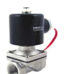
I searched for three-way 12VDC solenoid valves in stainless steel, but I could not find any valves at reasonable prices. I opted, instead, for two pairs of one-way valves—a normally closed (NC) and a normally open (NO) valve for each circuit. I found Echotec valves (see Figure 18) at http://stores.ebay.com/valves4projects for a little over $40 apiece for the 1/2-inch size and about $60 for the 3/4-inch size.
Reject Circuit(Figure 19): There is a connecting hose between the product water hose leading to the tanks and the hose that rejects and directs brine water overboard. There is a “NO” valve in the tank hose and a “NC” valve in the connecting hose. When an alarm signal is sent from the TDS meter it energizes the two valves. The “NO” valve in the tank hose closes and the “NC” valve in the connecting hose opens. The result is that the excessively saline product water is prevented from reaching the tanks and is forced overboard. The same result can be achieved by engaging the “Reject” switch on the control panel.
Flush Circuit: (Figure 20) Engaging the “Flush” switch on the panel energizes another pair of solenoid valves. An “NC” valve plumbed to the output of the carbon filter opens while an “NO” valve in the raw water intake closes. As a result, fresh tank water is pushed through the system in place of raw water. The reject switch is engaged during this operation, directing the flush water overboard.
O. Low-Pressure Hose and Connections: The hose runs from the engine room to the control panel and back, so I wanted hose that would flex without crimping. They are 1/4-inch ID hoses, and even though the pressures are small there
is as much as 3.6 gallons per minute flowing in some of them, so I did not want to use barb connections that would restrict flow. I finally settled on LDPE hose (low-density polyethylene) and Watts Quick-Connect fittings. Since the hose fits into the fitting, the fittings do not restrict flow like a barbed fitting does. Also, the Quick-Connect fittings allow for easy assembly or disassembly if I have to remove the control panel or any other components. The remaining hose is standard Shields 168 water hose.
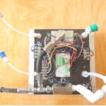
P. Installation: The control panel (Figure 23) was installed in a cabinet in the saloon above the engine room, so the first step was to cut access ports to allow wires and hoses to pass from the control panel to the engine room. Next, the subpanel assembly (Figure 24) was mounted to the port bulkhead in the engine room, more or less under the control panel.
The motor and pump shafts are joined by a bell housing and a “flexible” coupling for which the manufacturer has specified a gap of 1/8 inch. Setting the gap involves securing the coupling halves to their respective shafts with set screws. I found it easiest to assemble the system prior to installation then dismount the pump from the motor. This can be done without disturbing the gap setting. The motor was then installed on a vibration-dampened platform in the engine room.
Subsequently, the pump was reattached to the motor, thus maintaining the gaps. Since all wires and hoses had to pass between decks, I needed a way to identify them at each end of their runs. So, I made a wiring harness comprised of seven different colors. These colors matched those on the control panel and on the subpanel. Similarly, the hoses were marked with colored electrical tape before they were pulled through their runs.
The reverse osmosis membrane was installed into the pressure housing and the assembly was mounted to the engine room’s overhead using previously fabricated brackets. I made sure to take note of which direction the water was flowing. The remaining high-pressure hydraulic hoses were cut to length and their respective JIC fittings were attached. Care was taken to protect adjacent equipment from any potential leaks. Then, the wiring harness was connected to the control panel and subpanel assembly. The remaining hose connections were completed. Finally, the wiring connections to the ship’s AC and DC power supplies were made using appropriately sized wire and circuit breakers.
The project took about 12 hours to assemble and approximately 15 hours to install. Of course, this does not count the considerable time required to research and design the system, or to acquire the components.
Q. PERFORMANCE: During our 2012 cruise along the British Columbia coast, the system made 1,886 gallons at an average of 23 gallons per hour. The TDS in the product water consistently tested at 7 ppm. The only maintenance required was the periodic changing of the prefilters about every 15 hours of running time.
Useful Websites:
http://www.pipeflowcalculations.com/pressuredrop/
http://www.pressure-drop.com/Online-Calculator/index.html
http://www.cerusind.com/amperagecalc.asp
http://beta.circuitwizard.bluesea.com/#
http://www.csgnetwork.com/wiresizecalc.html
http://www.engineeringtoolbox.com/
http://www.thepurchaseadvantage.com/
http://www.americanro.com/index.html
http://www.frontpanelexpress.com/
http://www.omega.com/green/gsc.html
CAT 247 Specs 231.pdf (application/pdf Object)